 |
Socket Safety Shutters various mechanisms explained |
info page |
classic plugs |
| Safety shutters have been designed to
avoid that children and thoughtless adults put other objects than plugs
into domestic sockets. This preclusion applies also to adapters that
may stay,
unused, under tension. The preferred mechanism opens shutters only by pressing down both pins simultaneously. It is less safe if a single pin, or any other stylus can press the shutter away. Schemes A - E show types of safety shutters found in museum collection material. A brief description is given below. Images 1-10 show safe sockets and adapters in detail. An ingenious, now obsolete, Swedish shutter variant is shown at the bottom of page. |
| Top row: shutter (red) shields contacts (black) Bottom row: shutter has been pushed away by plug pin(s) [not shown]. |
 |
 |
 |
 |
 |
 |
| A |
Shutters are pushed away by pressing down
the earth pin. A very common mechanism found on most British sockets;
both BS 1363 (see image no. 1) and round pin BS 546 sockets. It has also been found on Australasian type sockets that have angled N and L contacts. |
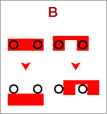
| B | Simultaneous pressing both N and L plug
pins pushes the shutter aside, in one or another direction. Common
mechanism for non-earthed sockets, but also applicable to earthed
sockets. See images 2-3 for details. |
| C | Simultaneous pressing down both pins of a
non-earthed plug rotates the shutter to a position that makes contacts
accessible. See images 4-6 for details. |
| D | Rotating shutter is a relative large
round plate that is a part of the socket housing. Plate is rotated by
pins of an non-earthed plug. A not often used system anymore, except
for
added later, stick-on type shutters. See images 7-9 and add-on nos
10a,b
for details. |
| E | Shutters
flip down by a straight blade
plug. A mechanism that has been found on American NEMA 5-15 sockets. A
coordinated action of both blades is not necessary; each
shutter flips independent of the other. It might be that implementation
of mechanisms A or B is difficult and C and D are impossible because of
the relative long, but narrow shutters |
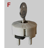
| F | Plug with key lock making socket inaccessible for any other plug. Click plug for details. |
 |
| 1 | Shutter
system pioneered by MK Electric in 1928, improved 1936 and still
in use for BS1363 and BS 546 sockets. Shutter (grey) covers line (L) and neutral (N) contacts (a, b). When inserting a plug, the long earth pin pushes the shutters aside (c). A spring (not visible) pushes the shutter back into safe position (b) when the plug is released. From 1984 BS 1363 plugs must have partially insulated line and neutral pins. Earth pins may not be insulated. |
 |
 |
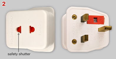
| 2 | Shaver adapter for British BS 1363
sockets, with - compulsory - safety shutter (red). Adapter has a 1A BS
646 fuse. The adapter accepts BS 4573 shaver plugs, Europlugs and US NEMA 5-15P flat blade plugs (non-polarized type only). Manufacturer: PMS Electrical Manufactury Ltd. Dating: 1984 or (probably) later, because L and N pins have insulating sleeves. |
| 3 | The shutter is a bar. Two springs
keep the bar in 'close' position. Left and right part of the bar have a
triangular shape (see upside down image). Because of the triangular
profile, pushing down both pins
of a shaver plug moves the shutter away. Attempts to push the shutter away by a single pin will fail, because exerting pressure on one shutter end, pulls the shutter out of position, resulting in too much friction for any further movement. |
 |
 |
 |
 |
| 4 | Shaver adapter for BS 1363 sockets; type
number 5120, made in Hong Kong. Adapter has a 1A BS 646 fuse. The adapter accepts BS 4573 shaver plugs, Europlugs and US NEMA 5-15P flat blade plugs (non-polarized type only). Manufacturer: not indicated. Dating: before 1984, because the plug has not yet partially insulated L and N pins. |
| 5a | Adapter inside views with shutter that
closes the plug pin inlet. Adapter L and N contacts are inaccessible.
The center position of the shutter is fixed. A spring pushed the
shutter against the top part of the adapter. |
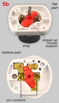
| 5b | Simultaneous insertion of both plugs pins
pushes the shutter down and aside, resulting in a approximate 60
degrees rotated position. Pin contacts are now accessible. After plug
removal, the spring will help the shutter to rotate back to the 'close'
position (image no. 5a). Shutter rotations are explained in detail in
image no. 6. |
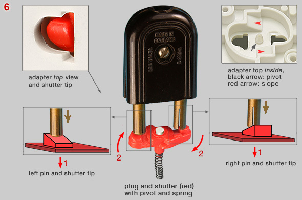
| 6 | The shutter in 'close' position is locked
in the plug pin inlet hole of the adapter housing; see inset top left.
Shutter tips have a sloped profile. Slope direction of one tip is
opposite to the direction of the other tip (compare schemes of left and
right shutter tip). Simultaneous* insertion of both plug pins starts the following process: (1) pins pushes the shutter about 2 mm down. The shutter is no longer captured in the adapter housing. (2) because of the sloped shutter tips, further pushing down pins forces the shutter to rotate. During rotation the shutter touches slopes that are part of the adapter housing (see red arrows in right inset). Pushing the shutter further down presses the spring. (3) finally, pins will touch the adapter contacts (visible in bottom image 5b). * a single pin can't rotate the shutter, because the other shutter tip remains captured in the adapter housing. Both the pressed spring and slopes of the adapter housing will result in bringing back the shutter in 'close' position as soon as the plug is pulled out. |
 |
 |
 |
 |
| 7 - 9 |
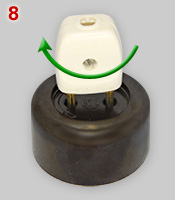
Bakelite 10A-250V socket with rotating shutter mechanism that is an intergral part of the socket housing. A partially inserted plug is used first to rotate the round shutter plate 90 degrees, then the plug can be pushed fully down to make contact (images 8 an 9), After releasing the plug, a spring ensures that the shutter rotates back to its 'close' position automatically. Manufacturer: NIKO, Belgium. Dating: 1950s - '60s. |
 |
| 10a | Bakelite
safety adapter with a child-safe locking mechanism comparable to NIKO
socket no. 7. Adapter pins have a length of 19 mm, identical to common
plug pin length*. The adapter can be used on most
two-pole socket, but is incompatible with Schuko sockets. Name of
manufacturer is not indicated. * The 19 mm pins make sufficient contact between adapter pins and socket contacts. This is an important feature; read also the comments to the add-on shutter shown in image 10b. |
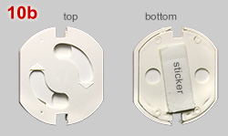
| 10b | Simple
add-on shutters,
without pins that can be fastened on top of a socket with
double sided adhesive tape. The stick-on shutter fits in not earthed
CEE 7/1 and earthed CEE 7/3 (Schuko) sockets. Shutters and tape is 4 mm thick, which means that a plug can be inserted 4 mm less deep in a socket and the plug pin contact zone is considerably smaller. That may result in overheating, depending on the current needed for the attached appliance. |
| An
ingenious child safe shutter mechanism was invented by Tage
Arnold Davidsson from Gotenburg, Sweden. The Swedish patent was claimed
December 23, 1952 (SE316003X). US patent application was filed in 1953. Sweden started in the mid 1960s a 10-years program to built each year 100,000 homes. The most popular sockets to be installed had Davidsson's child safe shutters, made by Eljo Plastindustri AB. Source of information and image no. 13: Ian Bakke, Sweden. |
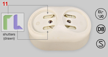 |
11,
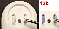
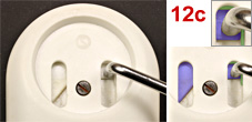
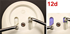
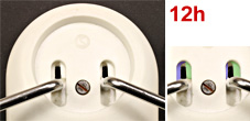
12 Duplex socket with "Davidsson" shutters. Rating 10A - 250V. Cast and shutter are made of a thermosetting plastic, socket body of steatite. The socket has three marks: (1) EL- -JO and, (2) DB refer to the name of the manufacturer, and (3) Swedish Semko certification mark. Dating: 1950s. {WN} Shutters have to be shifted aside by a sliding movement of both plug pins. Images 12a-h below show that access to contacts is not possible with a single pin. Images of artificially coloured shutters have been added to explain shutter mechanism. |
 |
a: each
outlet has two shutters. The
green shutter is operated by the right plug pin; the blue shutter by
the left pin. b: when moving the right (fake) pin upwards, the green shutter - in both the right and left slot - is sliding to the right. |
 |
 |
c: right pin
is moved fully upwards. Green shutter does not block the
slots anymore, but pin can not be inserted because of the blue shutter,
positioned under the green shutter
(see insert). d: the left (fake) pin has been added. |
 |
 |
e: when
moving the left pin upwards,
the blue shutter moves to the left in both the left and right slot. f: when left pin is in top position there is no obstruction anymore to insert both pins. |
 |
 |
g: when only
the left pin is used the pin can move upwards to a
position halfway only. Green shutter blocks further movement. h: only a simultaneous upward movement of both pins will result in sliding away both shutters. |
 |
 |
13 Schuko socket with Davidsson-type safety shutters. Image no. 13 is 180° rotated compared to no. 12. Earthed sockets were aimed for installation in kitchens, other rooms had the not earthed version. Manufacturer: socket has a DB (Dala-Bakelit) logo; DB was bought in 1945 by Joel Olsson's Elektriska AB. Tage Arnold Davidsson's shutter system is no longer in production. Manufacturing the relative complicated mechanism could have been insufficiently cost effective. |
 |
 |
 |
 |
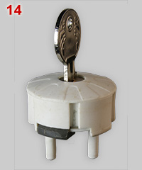
| A very different device to lock a socket that has earth clips. Probably not primarily designed for child safety. Preventing misuse of sockets in public space seems more likely; see also British Walsall sockets (nos 12-15) Manufacturer: not indicated; dating: unknown. {MN} |
|
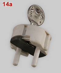
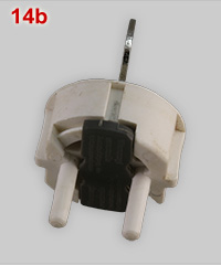
| 14 | Plug with two plastic 4.8 mm pins that fit in Schuko sockets. Plug has a 38.0 x 13.8, 4.8 mm tick black plastic plate. The key can turn the plate 45 degrees; compare plate position in images 14a and b. |
| 14a | Black shutter plate in 'open' position. Plug can be plugged in a Schuko socket. |
| 14b | Shutter plate in 'lock' position by rotating the key 45 degrees anti-clockwise. See also image 15. |
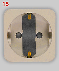
| 15 | Schuko earth clips block the plug. Only in this position it is possible to remove the key. Without key nobody can use socket. Note: the shown dark grey shutter plate is a carton replica. |
| |
D i g i t a l M u s e u m o f | |
P l u g s a n d S o c k e t s | |